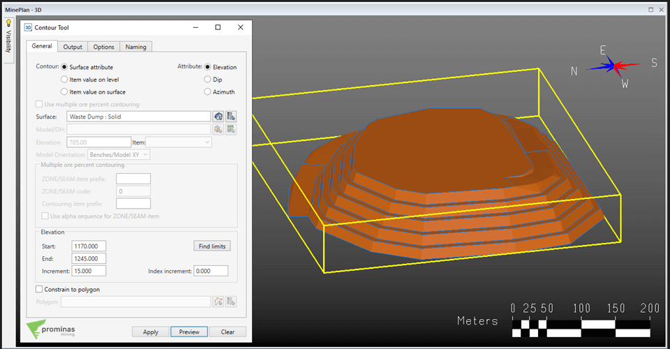
Contour Tool : Practicality and effectiveness when creating contour lines of a solid or surface. Did you know that MinePlan 3D has a tool that allows you to create contour lines from a solid or surface? The Contour Tool allows you to automatically create contour lines from surfaces or solids. It can be used to generate the contours of a topography, or the toe and ridge lines of a pit design, for example. To do so, simply access the tool from the Polyline or Surface menus. You must then select the required geometry, and define the elevations at which you want to create the contour lines. In the Elevation section, the Find Limits option can be useful for finding the vertical limits of your element. The Increment box allows you to define…
HxGN MinePlan
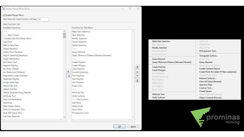
Popup Menu Definition: Customizing shortcuts for MinePlan 3D. Did you know that MinePlan 3D (MP3D) has a feature that allows the configuration of shortcuts accessible by the right mouse button? The Popup Menu is one of the main tools for defining shortcuts within MinePlan, in addition to providing access to recently used functions. By default, the tool is defined by the last ten functions used, and when accessing the Popup Menu Definition, located in the Menu Viewer, you can perform customizations. By opening the tool and enabling it, it is possible to add functions to the Static Functions List, which will always be visible when using the Popup Menu. To do so, just click on the function, and use the right arrow, creating the list. The first two available options (“—–” and “—– New Column”) are for better organization of sections…
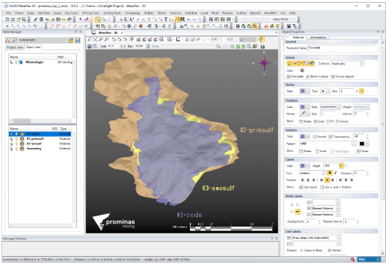
Materials: Assigning characteristics and values to elements. Did you know that it is possible to associate an attribute with several elements of a single object? Materials define the display attributes of MinePlan elements and data and can be accessed in the project's “_msresources/materials” folder. They allow you to associate a common set of attributes to several MinePlan elements at once, such as color, visibility and labels, as well as defining specific values to use when coding other objects, or even a block model. In a project, for example, with several lithologies, each one can be associated with a Material so that the visualization is different between them. This procedure can be performed using the Attribute Tool located in the “Element” menu. Figure 1: Material allocation by lithology. Wassup, did you like this tip? For more information about Materials, in addition to…
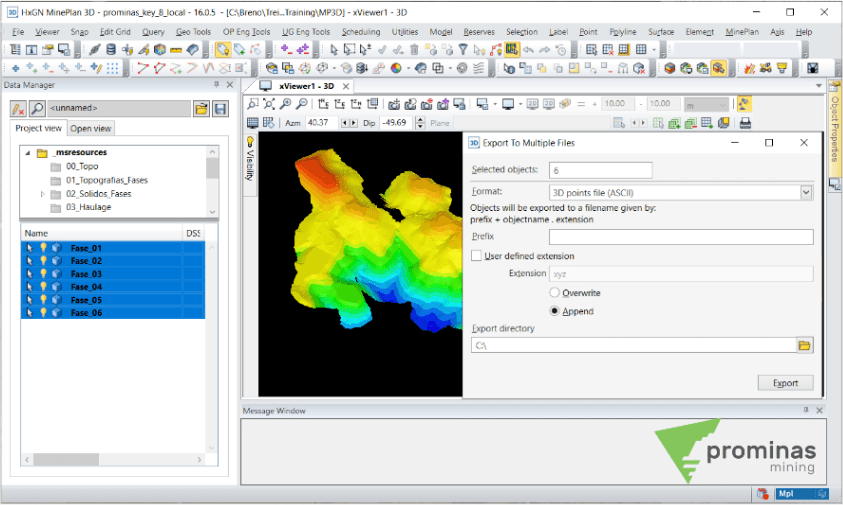
Export to Multiple Files: Export objects to multiple files automatically. Did you know that MinePlan 3D (MP3D) has a feature that allows you to export a set of objects to external formats automatically? The Export to Multiple Files functionality is accessed by right-clicking on the group of objects selected to export, via the path Export > Export to Multiple Files. This option differs from other exports, as it creates a destination file for each selected object, automating the export process. Figure 1: Export to Multiple Files. This way, in addition to making it possible to export objects to several files in all formats available in MinePlan, it also allows the application of some prefix in their naming and the option of overwriting or adding to files that already exist in the destination path. And then, did you like it...
Polyline Snap : Using Snap on polylines to scan sections automatically. Did you know that MinePlan 3D (MP3D) has a feature that allows you to use Snap on polylines and take advantage of existing objects? The Polyline Snap option allows using the points belonging to an existing polyline or polygon to guide the creation of new elements. This snap can be enabled through the Snap menu or using the keyboard shortcut number 4. When drawing a new polyline or polygon, just click on a starting point and an ending point of an existing element. The shorter segment, located between these two points, will then be digitized in the created element, being highlighted in Highlight with a greater thickness, as shown in the following figure. When pressing the Delete or Backspace keys right after placing the point…
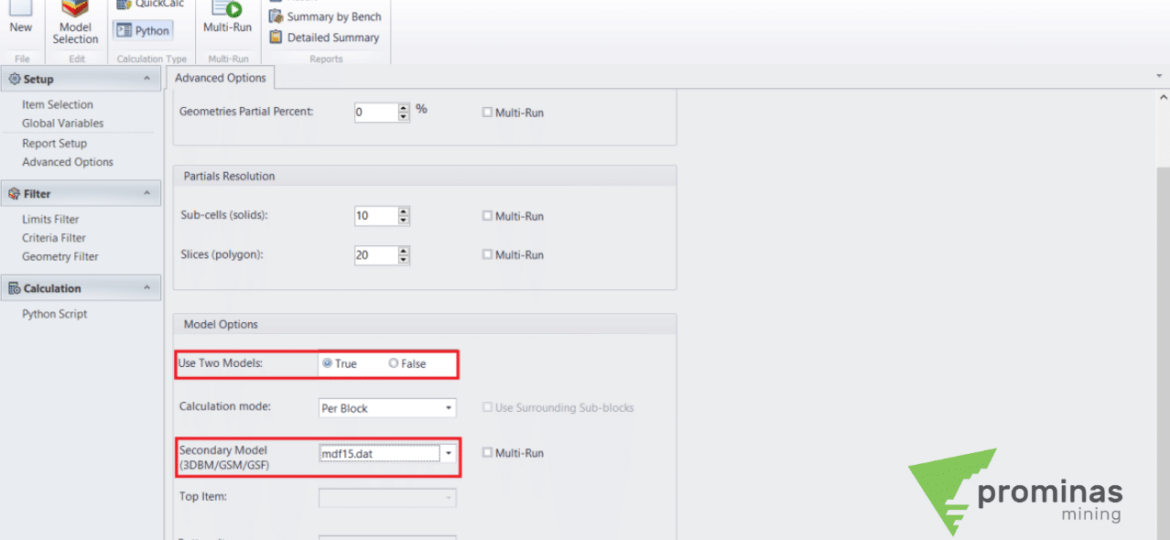
Model Calculation Tool: Performing calculations on the block model using information from a secondary model. Did you know that MinePlan 3D (MP3D) has a feature that allows you to perform calculations with two models simultaneously? The Model Calculation Tool (MCT), located in the Model menu, allows the user to quickly and conveniently perform calculations on MinePlan models (3DBM, GSM and GSF). It is common to need to cross information between different models, and through the Use Two Models option, located on the Advanced Options tab in the MCT, it is possible to map a secondary model. The secondary model can be in 3DBM, GSM or GSF formats, as long as it is contained in the same PCF (10.dat file) as the primary model. Figure 1: Model Calculation Tool with secondary model. Activating this functionality, on the Item Selection tab of the MCT, it is possible to select the variables to be…
Model Calculation Tool : Using information from surrounding blocks in model calculations. Did you know that MinePlan 3D (MP3D) has a feature that allows you to access information from adjacent blocks, while performing calculations on the block model? The Model Calculation Tool (MCT), located in the Model menu, allows the user to quickly and conveniently perform calculations on MinePlan models (3DBM, GSM and GSF). Using the MCT to manipulate 3D block models applies the instructions configured in each block of your model. However, it is also possible to enable information from surrounding blocks to be used in calculations. This functionality opens up opportunities for routines to have geometric dependencies and manage to add more information, such as dilution, reconciliation, operability evaluation, among others. To enable this functionality, just access the Advanced Options tab and, in Calculation Mode,…
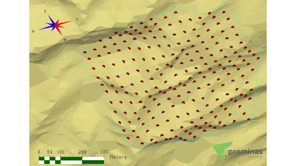
General Gridder Tool: Creating regular grid points on any triangular surface. Did you know that MinePlan 3D (MP3D) has functionality that allows you to create regularly spaced points on any surface? Located in the Points Menu, the General Gridder tool allows the creation of regularly spaced points on any triangular surface (Geometric Objects, Views of Geometric Objects and Large Gridded Objects – LGO's), storing the elevation of the surface at each grid point. The only input data requested by the tool is the surface where the points will be created, and in a complementary way, polygons can be used to limit the area. Furthermore, an Edit Grid can be used for the orientation of the points, and the minimum and maximum limits in each direction can be set manually. Figure 01 shows a preview of the points to be generated,…
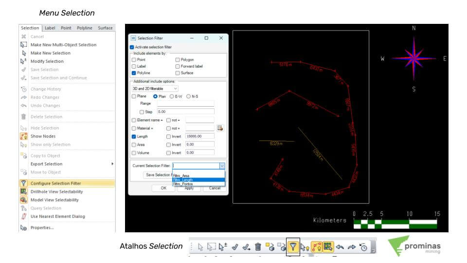
Selection Filter: Using filters to select elements. Did you know that MinePlan 3D (MP3D) has a feature that allows you to filter elements for selection in xViewer? When using the Selection menu in MP3D, there is an option to create filters for the selection of elements directly by xViewer (Selection > Configure Selection Filter). These filters can cover one or more types of elements: Points, Polygons, Polylines, Surfaces, Labels and Directional Labels. Furthermore, additional options can be set for more detailed selection: selection of 2D and/or 3D data; selection guided by planes (Planar, East-West or North-South) with the application of a range; selection from the Element Name or Material Name of the elements; and geometric selections, based on the length, area or volume of the element. Figure 01: Selection Menu (on the left); Selection Filter tool (right);…
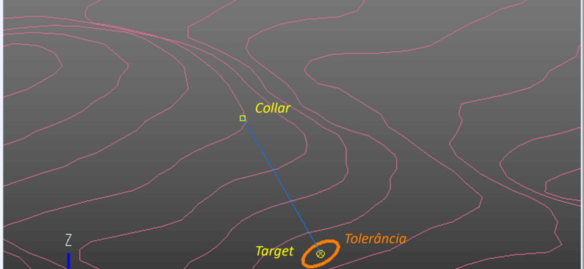
Did you know that it is possible to quickly generate drilling holes using directional and geological parameters in MinePlan 3D? In this article, we will explore how the Drillhole Design Tool can facilitate the planning of drillhole trajectories, optimizing processes and results. What is the Drillhole Design Tool? The Drillhole Design Tool, located in the Geo Tools menu of MinePlan 3D, is a powerful tool that allows you to plan the trajectory of a drill hole using previously established polylines. You can enter data directly into xViewer or by defining coordinates, ensuring accuracy and efficiency. Drillhole Design Tool Configuration Modes When opening the Drillhole Design Tool, you must define a name for the hole and choose one of the available configuration modes: Use existing polylines: allows you to select polylines already drawn in xViewer. The option…


